
Every HVAC project comes to the same question: how much resistance do flexible fabric ducts really have? Higher resistance means higher fan static pressure and higher electricity bills for years; lower resistance means a more efficient system. "Non-metallic composite duct" and "flexible fabric duct" are exactly the terms customers search before making a choice. This article answers with measured data from the report Friction Performance Comparison: Flexible Fabric Ducts vs. Galvanized Ducts.
First, clarify the duct categories
Based on 08K508-1, JG/T 258-2018 (Non-Metallic and Composite Air Ducts), GB 50736-2012 and ASHRAE data, the report divides ducts into three types:
- Galvanized metal ducts: spiral round and rectangular lock-form galvanized ducts with airtight walls.
- Rigid insulated non-metallic composite ducts: polyurethane, fiberglass and steel-faced phenolic composite ducts; walls are airtight with no air leakage.
- Flexible fabric ducts: further split into non-permeable (dense coated polyester, no wall air leakage) and permeable (porous fiber textile, uniformly permeable across the wall).
This distinction matters: permeable fabric ducts follow a completely different resistance calculation logic from the others, and most industry confusion comes from mixing them up.
Wall friction coefficients: the measured picture
Comparing wall friction only (measured at 6-9 m/s turbulent flow):
- Spiral round galvanized duct: roughness 0.05-0.10 mm, friction factor 0.018-0.020
- Steel-faced phenolic composite: 0.08-0.12 mm, 0.019-0.021 (up to +6% vs galvanized)
- Polyurethane composite: 0.20-0.30 mm, 0.021-0.025 (up to +20%)
- Non-permeable fabric duct: 0.22-0.35 mm, 0.022-0.026
- Permeable fabric duct: 0.30-0.48 mm, 0.026-0.030
- Fiberglass composite: 0.80-1.00 mm, 0.026-0.032 (+20% to +55%)
Conclusion: on wall friction alone, fabric ducts are not smoother than metal ducts. The raised fibers make them rougher, consistent with neutral fluid-dynamics measurements.
Specific friction loss at constant airflow
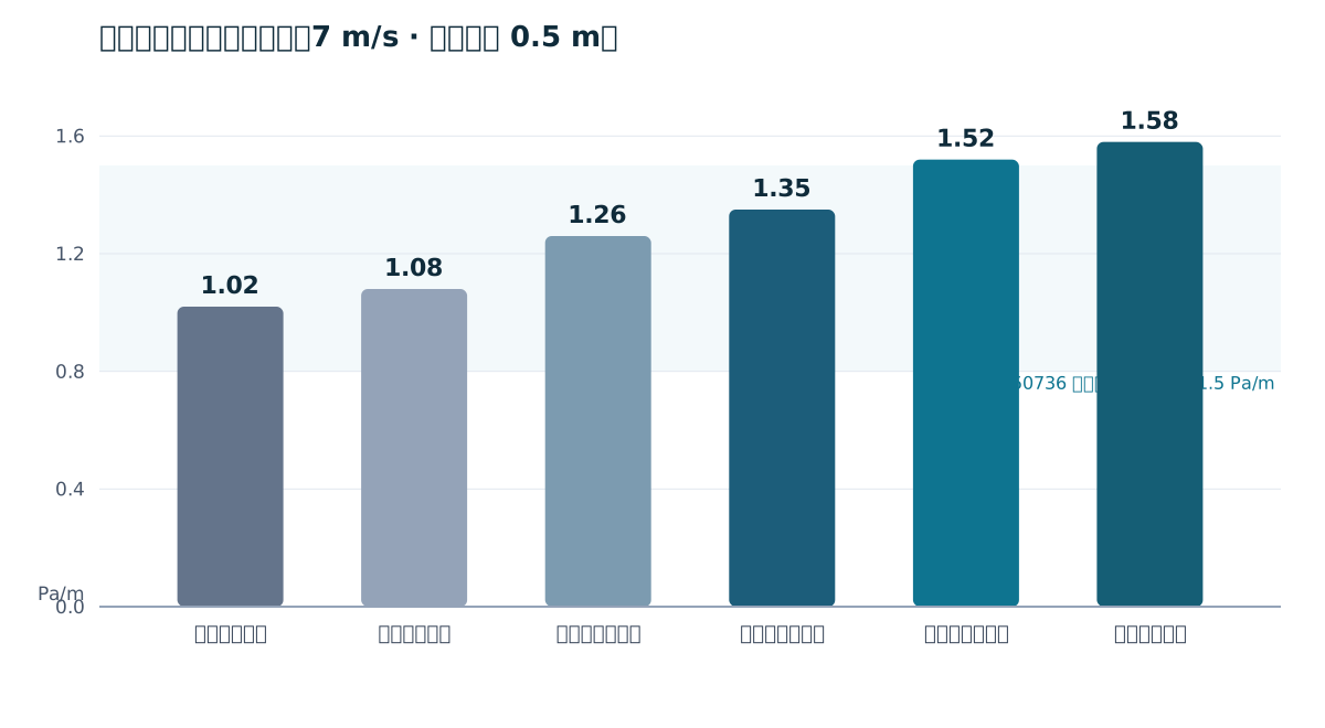
At a hydraulic diameter of 0.5 m, air velocity 7 m/s and no wall leakage (see chart above):
- Spiral galvanized duct: approx. 1.02 Pa/m
- Steel-faced phenolic composite: approx. 1.08 Pa/m (+6%)
- Polyurethane composite: approx. 1.26 Pa/m (+24%)
- Non-permeable fabric duct: approx. 1.35 Pa/m (+32%)
- Permeable fabric duct (theoretical, no leakage): approx. 1.52 Pa/m (+49%)
- Fiberglass composite: approx. 1.58 Pa/m (+55%)
GB 50736 recommends an economic specific friction range of 0.8-1.5 Pa/m. Fiberglass composite and permeable fabric ducts easily exceed this at 7 m/s, so engineers usually enlarge duct size and lower velocity to control resistance.
The "resistance puzzle" of permeable fabric ducts
If wall friction is not an advantage, why do some on-site measurements show very low resistance for fabric duct systems? The answer is permeability: while running, a permeable fabric duct releases 5%-15% of total airflow through the wall, so velocity decays continuously along the duct. Since resistance is proportional to the square of velocity, friction loss in the second half drops sharply. On a single long straight run with no branches, the full-length weighted average specific friction is only 0.35-0.6 Pa/m.
Three clarifications are essential:
- Weighted average resistance cannot be read directly from 08K508 tables, which assume airtight ducts at constant airflow.
- The low resistance comes from velocity decay, not a smoother fabric wall; wall friction alone is worse than galvanized.
- The advantage applies only to single long straight runs; with more elbows, reducers and tees, local resistance grows and the advantage shrinks sharply.
Whole-system resistance: what really drives fan selection
Fan static pressure is sized by total system resistance (friction + elbows + reducers + plenum + fittings):
- Galvanized steel duct system: 1.4-2.8 Pa/m (local losses 50%-70%)
- Rigid non-metallic composite duct system: 1.8-3.3 Pa/m
- Non-permeable fabric duct system: 1.6-3.0 Pa/m
- Permeable fabric straight-run system (few elbows, no multi-branch): 0.7-1.3 Pa/m
Design velocities and hydraulic calculation advice
- Round galvanized duct 7-10 m/s; rectangular galvanized up to 8 m/s;
- Fiberglass composite up to 8 m/s; resistance rises sharply at high velocity;
- Non-permeable fabric duct 7-9 m/s, designed like metal ducts;
- Permeable fabric duct inlet 7-9 m/s; mid and end velocities decay naturally with bleed air.
Key reminder: never apply a single specific friction value to the whole run of a permeable fabric duct. Calculate remaining airflow and velocity segment by segment, sum friction and local losses, and keep a 15%-20% fan static pressure margin. Asking the manufacturer for a hydraulic calculation report is the most direct way to avoid undersized fans and underperforming delivery.
Wrap-up
The resistance of a fabric air duct (bag duct, cloth duct) depends on whether it is permeable or not, how long the run is and how many fittings it has - there is no one-size-fits-all answer. RyboTex (Nantong) focuses on fiber fabric air ducts and insulation systems, providing CFD airflow simulation, anti-condensation calculation and standardized hydraulic design services.
Rybotex (Nantong) New Materials Co., Ltd. (brand RyboTex) focuses on fiber fabric air ducts and thermal insulation materials, offering CFD airflow simulation, condensation calculations and full-lifecycle technical services.